Introduction
Picture a busy intersection at 6 PM when the power drops. Signal heads go dark. Drivers treat the intersection like a four-way stop, except nobody agrees on whose turn it is. Within seconds, a routine commute turns into a collision risk.
Transfer relay switches exist to prevent this exact scenario.
A transfer relay switch is the device that automatically shifts an electrical load from a primary power source to a backup source the moment it detects a failure. No human intervention is required. In traffic cabinets, this same mechanism keeps signals cycling during outages and forces intersections into safe flash mode when something goes wrong internally.
This article breaks down how transfer relays work, the different types on the market, and why they're a non-negotiable component in traffic signal and ITS infrastructure.
Key Takeaways
- Transfer relay switches sense power loss and automatically reroute the load to backup power.
- Internal coils and contacts physically move the connection, similar to a solenoid.
- In traffic cabinets, relays enable battery backup switching and fail-safe flash activation.
- Automatic Transfer Switches (ATS) and Static Transfer Switches (STS) differ mainly in transfer speed, cost, and load criticality.
What Is a Transfer Relay Switch?
A transfer relay switch is an electromechanical device that uses relay or contactor logic to keep connected equipment powered by whichever source, primary or backup, is currently live. The moment the primary feed drops, the relay does the work of physically reconnecting the load elsewhere.
The core function is simple: sense the loss (or return) of the primary source, then switch the load's power path automatically. This protects equipment from downtime without anyone standing by with a wrench or a switchboard.
Inside the Switch
Every transfer relay shares a handful of core parts:
- Energized coil – creates the magnetic field that moves the switching mechanism
- Normally-open/normally-closed contacts – physically complete or break the circuit path
- Control logic – often microprocessor-based, this decides when to trigger a transfer
- Interlock – a safety feature that prevents both power sources from connecting at the same time
The interlock is the single most critical safety feature in the assembly. Without it, you risk backfeeding a generator or, worse, energizing a line that a utility crew thinks is dead.
Note: "transfer relay" technically refers to the internal switching component, while "transfer switch" describes the full enclosed assembly. In the field, though, these terms get used interchangeably almost universally.
Where Transfer Relay Switches Are Used
Transfer relays show up anywhere uninterrupted power matters:
- Traffic signal and ITS cabinets requiring continuous, fail-safe operation
- Industrial facilities and data center backup systems
- Standby generators for homes and RVs
Capacity varies enormously depending on the application. Smaller residential and light commercial units run in the 30-50 amp range, while industrial-grade switches scale up to several thousand amps for large facilities.
Traffic cabinet applications sit at the smaller end of that spectrum, but a failed transfer here has outsized consequences: it can take an entire intersection dark.
How Does a Transfer Relay Switch Work?
Transfer relays run through a predictable sequence every time. Understanding each stage explains why these devices are reliable rather than reactive guesswork.
- Continuous monitoring – Control logic constantly checks incoming voltage and frequency from the primary source.
- Detection – When voltage drops below a preset threshold, or disappears entirely, the logic flags a failure condition.
- Delay/stabilization – The switch typically waits 10-40 seconds, giving a backup generator time to start and stabilize before any load transfers over.
- Switching action – The relay coil energizes, physically moving contacts so the load disconnects from the primary source and connects to backup.
- Retransfer – Once primary power is confirmed stable again, the process reverses: the load reconnects to the main source, and the backup de-energizes.
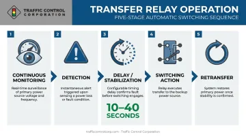
That delay stage is easy to overlook, but it's the difference between a clean transfer and a chaotic one. Switch too fast, before a generator has stabilized, and you risk feeding equipment with dirty or fluctuating power.
Manual vs. Automatic Operation
That precision means little, though, if the switch depends on someone being there to trigger it. Not every transfer switch senses and acts on its own.
Manual transfer switches require an operator to pull a handle or press a button to initiate the switch—simple, cheap, but dependent on someone being present. Automatic transfer switches, by contrast, sense the failure condition and complete the transfer without any human input.
For anything running unattended, and that includes nearly every traffic cabinet, automatic operation isn't optional. Nobody's stationed at an intersection controller waiting to flip a switch during a storm.
Types of Transfer Switches and Transition Methods
Not all transfer switches are built the same way, and the mechanism matters for both cost and application size.
| Switching Mechanism | Best Suited For |
|---|---|
| Power frame | High-capacity, high-speed industrial applications |
| Molded case | Mid-range commercial and light industrial loads |
| Contactor-based | Smaller, economical applications; widely used across generator backup systems |
Contactor-based switches dominate lower-capacity applications, including many traffic cabinet setups, because they balance cost with reliable performance.
Transition Types Matter Just as Much
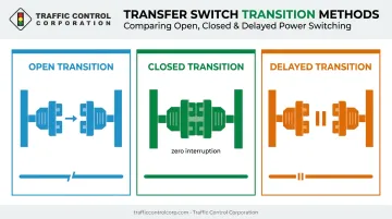
Beyond the switching mechanism itself, the transition method determines how the load experiences the switch:
- Open transition – A brief break occurs between disconnecting from one source and connecting to the other.
- Closed transition – Sources briefly overlap, delivering zero interruption to the load.
- Delayed transition – Adds a pause after disconnection to let residual voltage dissipate before reconnecting.
Which one you need depends entirely on how critical the load is. A facility running life-safety systems or public infrastructure, think traffic signals, often can't tolerate even a momentary blackout. That intolerance for downtime pushes design toward closed or delayed transitions rather than the simpler open-transition approach.
Transfer Relay Switches in Traffic Signal and ITS Systems
Traffic cabinets depend on transfer relays for two distinct, critical safety jobs:
- Switching to battery backup or UPS power the instant utility power drops.
- Forcing the intersection into flash mode when the conflict monitor or malfunction management unit (MMU) detects a fault condition.
The stakes here are not abstract. A dark or malfunctioning intersection is genuinely dangerous.
Research on traffic signal power outages found that dark-signal collisions are disproportionately right-angle crashes, accounting for 77.7% of related incidents, among the more severe crash types at intersections. That statistic explains why flash mode, not a dead signal, is the acceptable fallback.
Flash transfer relays work in tandem with NEMA-compliant conflict monitors to guarantee this outcome. Under NEMA TS 2-2021 standards, the MMU monitors for fault conditions, such as conflicting green indications, and de-energizes the flash transfer relay to drop the intersection into flash rather than allow an unsafe signal state to persist.
Battery Backup and UPS Integration
A transfer relay paired with a battery backup system (BBS) can keep signals cycling normally for a set duration during an outage. This keeps traffic moving during anything short of an extended blackout.
Because this relay sits at the center of a fail-safe chain, testing isn't optional. Routine signal maintenance programs should confirm that transfer relays switch correctly and on schedule, not just that they're physically installed and wired.
Traffic Control Corporation (TCC) supplies transfer relays, conflict monitors, and battery backup systems to agencies across the Midwest, drawing from manufacturers including Econolite, Alpha Technologies, and Reno A&E.
Beyond the hardware, TCC's factory-trained field service staff provide:
- Product selection and application guidance for cabinet upgrades
- Onsite troubleshooting when a relay or monitor fails
- Hands-on training so technicians aren't left guessing during a health check
ATS vs. STS: What's the Difference?
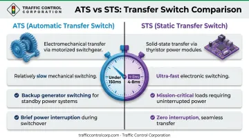
Both ATS and STS units do the same basic job: move a load between power sources. How they do it, and how fast, is where they diverge.
| Feature | ATS (Automatic Transfer Switch) | STS (Static Transfer Switch) |
|---|---|---|
| Switching technology | Mechanical/electromechanical relay contacts | Solid-state semiconductor switching |
| Transfer speed | Under 150 milliseconds | Roughly 4-8 milliseconds |
| Typical applications | Generator backup, standby power, traffic cabinets | Data centers, dual-utility feeds, mission-critical loads |
| Interruption tolerance | Brief gap acceptable | Near-zero tolerance required |
According to Eaton's transfer switch technical documentation, STS units complete transfers in roughly 4-8 milliseconds—dramatically faster than the under-150-millisecond gap acceptable for generator backup and standby power applications. That speed advantage is why STS units serve facilities running dual-utility feeds, where even a few milliseconds of interruption is unacceptable.
The tradeoff is cost and complexity. STS units run more expensive and demand more specialized maintenance than ATS. For most traffic infrastructure applications, that added cost doesn't buy enough benefit to justify skipping the mechanical relay approach.
Frequently Asked Questions
What is the function of a transfer relay?
A transfer relay senses when the primary power source fails and automatically switches the connected equipment's load to a backup source. Once primary power stabilizes again, it reverses the process and restores the original connection.
What's the difference between ATS and STS?
ATS uses mechanical relay contacts with a brief transfer delay, typically under 150 milliseconds. STS uses solid-state switching to transfer in a few milliseconds, making it the better fit for zero-interruption critical loads.
How do I know if a transfer relay switch is failing?
Warning signs include humming or buzzing from the relay, burned or pitted contacts, failure to energize after the expected delay, or intermittent power loss at the load. Any of these warrants inspection before the relay fails completely.
Can a transfer relay switch be used in a traffic signal cabinet?
Yes. Transfer relays are standard cabinet components used both for switching to backup power and for triggering flash mode when a conflict monitor detects a malfunction.
How often should transfer switches be tested or maintained?
Critical applications should follow a routine load-testing schedule set by the manufacturer or governing agency. Industry guidance such as NFPA 110 recommends monthly operational load testing for switches supporting emergency power systems.
What's the difference between automatic and manual transfer switches?
Automatic switches sense power loss and complete the transfer without human input. Manual switches require an operator to initiate the transfer using a handle or button.