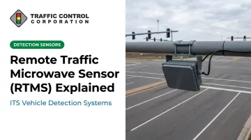
Agencies have been moving away from inductive loops for years. The FHWA's Traffic Detector Handbook notes that while loops remained the most widely used detector as of 2006, over-roadway sensors like RTMS had already emerged as a proven alternative that meets most freeway and surface-street requirements.
The catch: many agencies specify RTMS units without fully understanding how the radar detects, processes, and outputs data. That gap leads to poor lane configuration and mismatched use cases. This guide breaks down what RTMS is, how it works stage by stage, and where it actually delivers value.
Key Takeaways
- RTMS uses FMCW radar to track presence, speed, volume, and vehicle class across up to 12 lanes
- Side-fire mounting covers multiple lanes, while forward-fire/oblique setups handle only one or two
- MnDOT field tests recorded volume error as low as 2.4% and speed error as low as 4.4%
- No pavement cutting means faster installs and fewer lane closures than inductive loops
- Model selection and calibration require site-specific expertise, not a catalog purchase
What Is RTMS?
RTMS stands for Remote Traffic Microwave Sensor: a radar-based vehicle detection device that measures distance to objects within its beam. It identifies vehicles moving or stopped across multiple lanes at once.
A 1992 Transportation Association of Canada paper documents its origin as a project partially funded by the Government of Ontario. The goal: give agencies a radar alternative to embedded loops.
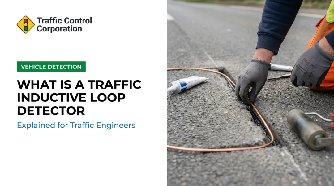
That origin matters because of the problem it solved. Inductive loops require cutting into pavement, which means:
- Lane closures during installation and every repair
- Wear-and-tear from traffic loads and resurfacing cycles
- Disruption whenever utility work touches the roadway
RTMS sidesteps all of that by mounting above or beside the road.
What RTMS is not: A video detection camera or a single-lane point sensor. It's a true multi-lane radar unit that reads an entire roadway cross-section from one mounting point.
RTMS still earns its place in a detection lineup where all-weather reliability and multi-lane coverage matter more than the lower upfront cost of a point sensor. On a six-lane freeway or a bridge deck where pavement work isn't practical, that trade-off usually favors radar.
Types and Configurations of RTMS
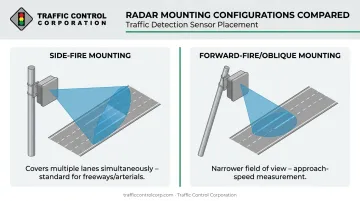
Two mounting approaches define how an RTMS unit "sees" traffic:
- Side-fire – Mounted on a roadside pole perpendicular to traffic flow, this configuration covers multiple lanes simultaneously. It's the standard setup for freeway mainline and multi-lane arterial monitoring.
- Forward-fire/oblique – Aimed at oncoming or receding traffic from an angled position. This mode narrows the field of view, generally to one or two lanes, but offers a different vantage point for approach-speed measurement.
Manufacturer generations matter here too. Legacy G4/K4 units support up to 12 single detection zones or 8 lanes in dual-loop-emulation mode, depending on configuration.
Newer Sx-300-generation and RTMS Echo sensors carry that same 12-lane ceiling forward but add features like integrated cameras and browser-based setup. The right pick depends on road geometry, lane count, and what data outputs the agency actually needs downstream — not just which unit has the higher spec sheet number.
How Does RTMS Work?
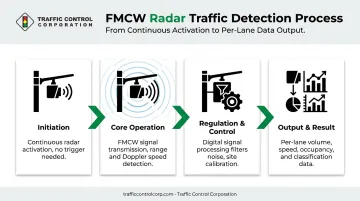
RTMS operation follows a defined sequence: initiation, radar transmission and reception, signal processing, and data output. Each stage shapes how accurate the final numbers turn out to be.
Initiation
Detection starts the moment the unit is powered and aimed at the roadway. It runs continuously and automatically: there's no trigger event, no single vehicle that "wakes up" the sensor.
Initiation depends heavily on physical setup. Pole height, aiming angle, and distance from the road all directly shape the detection zone's accuracy. Get any of these wrong, and the zone won't line up with actual lanes.
A common bottleneck here: incorrect installation angle or obstructed sightlines. Large trucks in near lanes can block the beam path to smaller vehicles in adjacent lanes, a known limitation of older-generation microwave detectors that still shows up on side-fire installs today.
Core Operation
The sensor continuously emits a microwave signal across the road surface using frequency-modulated continuous wave (FMCW) technology. As the FHWA explains, the transmitter continuously changes frequency, and because reflected echoes return after a time delay, the frequency difference between transmitted and received signals is directly proportional to range.
Here's what happens during operation:
- Reflected echoes bounce back from vehicles in the beam path
- Time delay in the echo reveals distance (range)
- Frequency shift in the echo reveals speed, via the Doppler effect
- The road surface is divided into individual per-lane detection zones
Detection speed and lane-splitting accuracy determine how reliably the sensor tells apart closely spaced or overlapping vehicles (the harder problem in congested, multi-lane traffic).
Regulation and Control
Raw radar returns aren't clean data. Onboard digital signal processing filters out noise from rain, snow, fog, stationary roadside objects, and other non-vehicle reflections to keep readings consistent.
Calibration happens during setup, matched to the specific lane geometry and mounting height at that site. Recalibration becomes necessary after road restriping or pole relocation: skip it, and the detection zones no longer line up with real lanes.
This stage is where accuracy gets made or lost. A MnDOT field evaluation of a pole-mounted RTMS unit found 24-hour volume error ranging from 2.4% to 8.6%, and speed error ranging from 4.4% to 9.0%, with congestion increasing error rates in both categories.
Auto-configuration handled volume setup fine, but speed and classification accuracy required manual, iterative adjustment. That's a strong argument for treating calibration as an ongoing process, not a one-time install step.
Output and Result
Once processed, RTMS delivers per-lane data:
- Vehicle presence and volume
- Occupancy and headway
- Average speed
- Vehicle classification
That data moves downstream via serial interface or contact closures to signal controllers, advanced traffic management systems (ATMS), or incident detection platforms.
Real-world scale shows what this looks like in practice. On the Mersey Gateway project near Liverpool, England, 55 RTMS G4 and Sx-300 radars were deployed across a new six-lane cable bridge and 5.7 miles of connecting road.
The system fed flow, speed, occupancy, headway, and classification data into the corridor's master-control system for real-time incident detection, supplying advance warning and helping prevent secondary crashes along the corridor.
Where Is RTMS Used?
RTMS shows up at four main points in a transportation network:
- Freeway mainline monitoring – tracking volume, speed, and incidents across multiple lanes
- Signalized intersection approaches – feeding adaptive signal control and left-turn detection
- Bridge and tolling corridors – where structural constraints make pavement cuts impractical
- Highway data collection stations – gathering long-term traffic pattern data
RTMS performs best on multi-lane roads, in all-weather environments, and at sites where cutting into pavement for loops would be costly or logistically painful — with steel bridge decks as the clearest example.
Beyond these physical conditions, use cases vary by context. Freeway deployments lean toward incident detection and ramp metering. Intersection deployments lean toward adaptive signal actuation. The underlying radar mechanics don't change between the two; only the application does.
Sourcing, Installation & Ongoing Support for RTMS Systems
Picking the right RTMS model, mounting configuration, and communication interface takes application-specific expertise. It's not a catalog checkbox exercise.
Consider what a mismatched spec actually costs an agency:
- Mounting mode that doesn't match the road geometry leads to missed detections
- An incorrect lane-count assumption leaves the unit unable to cover what the spec promised
- A flawed calibration approach produces volume and speed data that can't be trusted
This is where working with an established regional distributor pays off. Traffic Control Corporation (TCC), based in Woodridge, Illinois, has represented Image Sensing Systems, the original developer of RTMS, for years. The distributor also carries 40+ other ITS and traffic signal manufacturers across an 11-state Midwest territory.
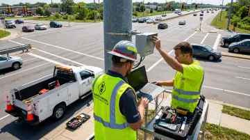
TCC's factory-trained technical staff provide product selection consulting, onsite troubleshooting, and detection systems turn-on service. Turn-on service covers setting detection zones, aligning sensors to approach lanes, and confirming that calls reach the controller correctly before an intersection goes live.
Ongoing support matters as much as the initial install. Road restriping, pole relocation, and normal drift all pull an RTMS unit out of calibration over time.
TCC's detection systems audit and health check service is built to catch misaligned radar and silent failures before they degrade intersection performance. This proactive check keeps volume and speed data trustworthy for years, not just at commissioning.
Conclusion
RTMS works by combining continuous radar transmission, real-time signal processing, and multi-lane data output to deliver accurate, non-intrusive traffic detection. Understanding each stage, from initiation through calibration to final output, is what separates a well-specified deployment from one that generates unreliable data or misses vehicles in adjacent lanes.
Getting procurement and deployment right starts with selecting the unit to match the site's traffic patterns and lane configuration. Agencies planning a new RTMS deployment or upgrading legacy detection across their network should consult an experienced regional partner like TCC before finalizing a spec.
Frequently Asked Questions
What does RTMS stand for and who manufactures it?
RTMS stands for Remote Traffic Microwave Sensor. The Government of Ontario partially funded its original development in the early 1990s, and Image Sensing Systems (ISS) later commercialized the technology.
How does RTMS differ from inductive loop detectors?
RTMS mounts above or beside the road, so it requires no pavement cutting, unlike loops embedded in the roadway surface. One unit also covers multiple lanes, reducing hardware needs and roadway maintenance disruption compared to loop-per-lane installations.
How accurate is RTMS in detecting vehicle speed and volume?
Accuracy depends on proper calibration and mounting height. A MnDOT field evaluation found volume error between 2.4% and 8.6%, and speed error between 4.4% and 9.0%, with congestion increasing error rates in both.
Can RTMS operate reliably in poor weather conditions?
Yes. RTMS units function as all-weather sensors, and radar signal processing filters out interference from rain, snow, and fog under normal conditions. Extreme weather events and heavy roadside contamination can still affect performance.
How many lanes can a single RTMS unit monitor?
A single unit can typically monitor up to 12 adjacent lanes in side-fire configuration, depending on the model and mounting setup. Forward-fire/oblique mounting generally narrows coverage to one or two lanes.
Is RTMS compatible with existing traffic signal controllers and ATMS platforms?
In most cases, yes. RTMS transmits data via serial interfaces or contact closures, which allows integration with most modern signal controllers and traffic management systems. You should still confirm specific compatibility against your existing cabinet and ATMS setup.