Introduction
Inductive loop sensors have been embedded in roadways since the early 1960s and remain one of the most widely used vehicle detection technologies in traffic management systems today. Sixty-plus years of continuous deployment is a practical endorsement of how well the technology performs.
The challenge most traffic engineers, DOT staff, and contractors face isn't understanding that loops exist. It's having a single, practical reference that covers the physics, the configurations, the applications, and the real-world trade-offs — without wading through scattered technical manuals or manufacturer spec sheets.
This guide covers all of it:
- How inductive loop sensors work at the component level
- The full range of loop geometries and their appropriate use cases
- Primary traffic applications from signal actuation to bicycle detection
- Installation and maintenance best practices
- An honest assessment of where loops excel and where they don't
Key Takeaways
- Inductive loops detect vehicles by sensing a drop in inductance when metal enters the electromagnetic field
- Loop size and geometry directly affect sensitivity — smaller loops often outperform larger ones
- Dual-loop configurations enable speed measurement and vehicle classification, not just presence detection
- Sealant application and electrical testing determine long-term service life more than any other installation factors
- Loops excel at point detection but cannot capture pedestrian, trajectory, or turning movement data
What Is an Inductive Loop Sensor and How Does It Work?
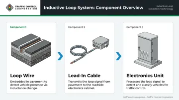
Every inductive loop system has three principal components:
- Loop wire — insulated wire laid in a shallow saw-cut slot in the pavement, typically wound in one or more turns
- Lead-in cable — a twisted-pair conductor running from the loop to a nearby pull box
- Electronics unit — housed in the traffic signal controller cabinet, it drives the loop and interprets detection signals
The Operating Principle
The electronics unit transmits alternating current through the loop wire at frequencies between 10 kHz and 200 kHz, creating a magnetic field around the loop. When a vehicle enters this field, two competing effects occur in the vehicle's metal:
- Ferromagnetic effect: The vehicle's iron mass slightly increases inductance by lowering magnetic-path reluctance
- Eddy current effect: Conductive metal generates opposing currents that decrease inductance
According to the FHWA Traffic Detector Handbook, the eddy current effect dominates — so the net result is always a reduction in inductance. That reduction is what triggers detection.
The electronics unit senses this inductance drop as a shift in the oscillator's resonant frequency, then outputs a signal to the traffic controller. This works in two modes:
- Presence mode: Output holds as long as a vehicle remains over the loop
- Pulse/passage mode: Output fires briefly (typically 100–150 ms) as a vehicle crosses
Sensitivity and Lead-In Cable
FHWA defines loop sensitivity as: SL = 100 × (LNV − LV) / LNV, where LNV is inductance without a vehicle and LV is inductance with one present.
Smaller loops generally produce higher sensitivity — not larger ones. When the loop area is small relative to the vehicle's undercarriage, the vehicle displaces a larger proportion of the detection zone, producing a greater percentage inductance change. Oversizing loops often produces worse detection, not better.
Lead-in cable length directly affects that sensitivity figure. Two key rules govern lead-in behavior:
- Twisted-pair lead-in wire adds approximately 21 microhenries per 100 feet (#14 AWG) to the system's baseline inductance — without adding any vehicle-caused change, which dilutes the sensitivity ratio
- FHWA requires a minimum of 5 turns per foot of twist to reduce noise pickup and crosstalk; longer runs make this even more critical
Types of Inductive Loop Configurations
Standard Short Loops
The 6 ft × 6 ft square is the most common configuration for signalized intersections. For narrower lanes, 5 ft × 5 ft loops reduce crosstalk — the false detection of vehicles in adjacent lanes. One firm rule: a loop should never be shorter than its width, or sensitivity loss follows.
Long Rectangular Loops
Ranging from 6 ft × 20 ft to 6 ft × 80 ft, long loops are used for large-area presence detection near stop bars on actuated signal approaches. They're effective for detecting stopped vehicles, but they tend to undercount volumes in high-density, stop-and-go traffic compared to advance short loops.
Multi-Loop and Dual-Loop Configurations
When loops are wired together, the configuration affects total inductance:
- Series wiring: Inductance adds up — raises total system inductance
- Parallel wiring: Inductance divides — lowers total system inductance
Dual-loop setups offer more than redundancy. Two loops placed a known distance apart enable speed measurement via travel time between detectors. Electronics units with waveform-signature capability can also produce vehicle classification data.
MnDOT testing achieved overall classification accuracy of 92.9%–93.8% across two sites, though class-level performance varied: Class 2 vehicles hit 99%, while Class 6 dropped to 51.6%.
Specialized Geometries
| Configuration | Use Case |
|---|---|
| Diamond-shaped loop | Bicycle detection in dedicated bike lanes |
| Quadrupole (figure-eight) | Reduced adjacent-lane splashover; small vehicle detection |
| Directional logic (two sequential loops) | Wrong-way detection, gate access control |
| Temporary/portable mat loops | Traffic studies, speed monitoring, weigh-in-motion |
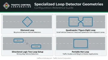
Diamond loops follow Oregon's 4 ft × 4 ft design or Caltrans Type D patterns fitted inside a 6-foot square. For directional configurations, detection sequence between the two loops determines travel direction. That said, a TxDOT/FHWA field test found surface-mounted directional loops achieved only 61% directional accuracy, suggesting redundant systems are worth considering for critical applications.
Key Applications of Inductive Loop Detectors in Traffic Management
Traffic Signal Actuation and Adaptive Control
Loops at signalized intersections provide the real-time vehicle presence and passage data that actuated controllers need to optimize phase timing. Placement matters: advance loops (placed 2–4 seconds of travel time upstream of the stop bar) serve different functions than stop-bar loops. Advance loops provide volume counts unaffected by queue backup; stop-bar loops confirm vehicle presence for phase hold decisions. Using the wrong placement for the wrong function introduces timing errors that compound across the signal day.
Vehicle Counting, Speed, and Classification
Single loops provide volume and occupancy data. Dual-loop "speed trap" configurations calculate speed from the known distance between loops divided by the measured travel time. One controlled test found a single-loop electronics unit achieved 1 miss in 1,923 vehicles — a 99.95% count accuracy — though that was a single 15-minute sample under favorable conditions. Real-world network accuracy varies: a weighted MAPE of 4.0%–45.5% across a monitored network reflects the impact of inspection and maintenance quality.
Freeway and Arterial Traffic Monitoring
High-speed corridor loops feed data to traffic management centers for incident detection, travel time estimation, and congestion monitoring. Advance detector placement is critical — loops positioned downstream of turn lanes or access points will overcount volumes by capturing vehicles that leave the facility before the intersection.
Parking Facilities and Access Control
Parking structures represent one of the most reliable environments for loop deployment. Sheltered from heavy truck loads and temperature extremes, loops in parking structures trigger gate mechanisms, dispense tickets, and track occupancy reliably for years. Directional logic setups distinguish entering from exiting vehicles at shared access points.
Bicycle Detection
Diamond-shaped loops installed in dedicated bike lanes can detect cyclists — even wheel rims generate a measurable inductance shift. Three factors determine reliable performance:
- Loop geometry: Diamond orientation maximizes the signal from a narrow bicycle wheel track
- Sensitivity calibration: Standard settings are insufficient; detectors must be tuned for small metallic objects
- Placement: Loops should be positioned advance of the stop bar to avoid false reads from stopped riders resting over the loop
Installation, Calibration, and Maintenance Best Practices
The Saw-Cut Process
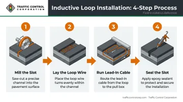
The standard installation sequence:
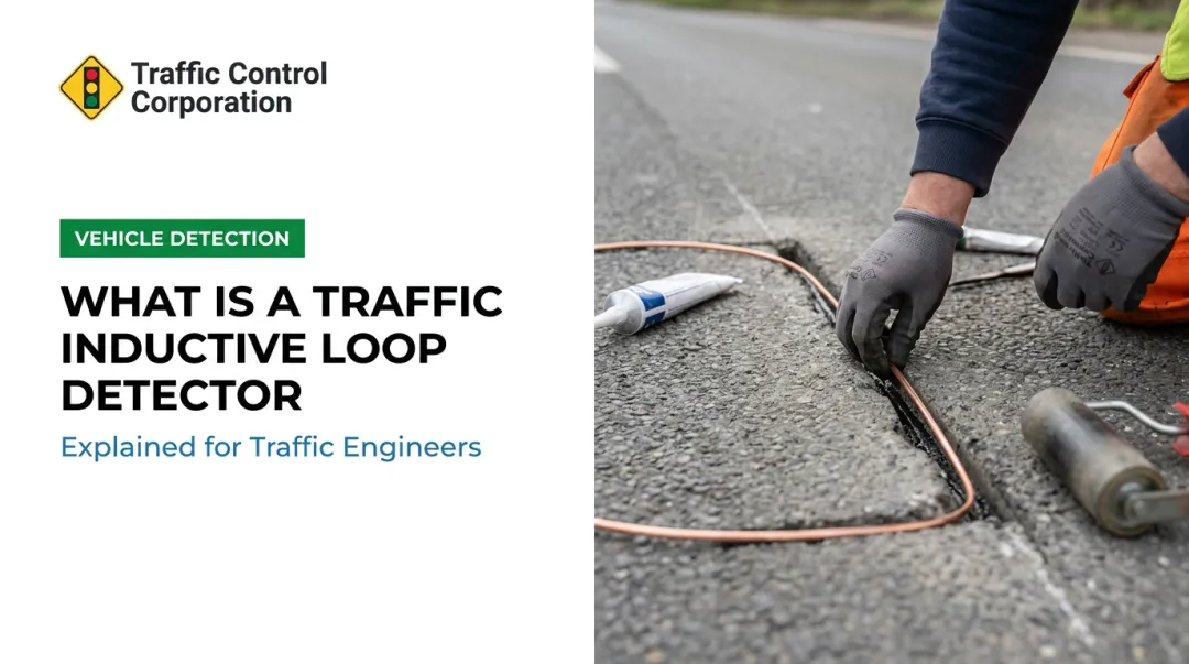
- Mill the slot — typically ¼ to ½ inch wide, cut into asphalt or concrete
- Lay the loop wire — wound in the required number of turns within the channel
- Run lead-in cable — routed to a pull box and then to the electronics unit in the signal cabinet
- Seal the slot — with a compatible, weatherproof loop sealant that maintains adhesion through freeze-thaw cycling
Improper sealing is one of the leading causes of premature loop failure. Moisture infiltration allows wire movement under traffic load, which fatigues insulation and opens circuits. FHWA favors cold-applied sealant materials over hot asphalt, which can damage wire insulation during application.
Loops should not be installed directly over existing pavement joints or wide cracks — pavement movement at those points will eventually damage the wire.
Electrical Testing Requirements
Complete electrical checks before and after sealing to catch problems while corrections are still straightforward:
- Verify continuity to confirm the wire circuit is intact
- Measure DC resistance — values should fall within approximately 10% of calculated figures
- Test insulation resistance — new installations should read more than 100 megohms at 500 V
- Measure inductance to confirm loop geometry and wiring configuration are correct
Calibration and Ongoing Maintenance
Set initial sensitivity to the lowest level that consistently detects the target vehicle class. Higher sensitivity increases detection reliability for small vehicles but also increases crosstalk risk from adjacent lanes.
Routine inspection should check for:
- Sealant deterioration or delamination
- Corroded splices at pull boxes
- Visible pavement cracking over the loop
- Sensitivity drift from moisture infiltration
Recalibration is required after pavement resurfacing — though FHWA notes resurfacing often necessitates loop replacement rather than just recalibration, depending on how much the pavement profile changes.
For agencies sourcing loop system components, TCC distributes EDI loop detector electronics in single, dual, and four-channel configurations compatible with NEMA TS-1, NEMA TS-2, ATC, and ITS cabinets. TCC also stocks Q-SEAL 290 S loop sealant by Chemque and provides product selection assistance and on-site technical support across its eleven-state Midwest service area.
Strengths and Limitations: What Traffic Engineers Should Know
Where Loops Excel
- Weather and lighting independent: Unlike camera-based systems, loops don't degrade in fog, rain, glare, or darkness
- Reliable occupancy data: FHWA identifies loops as the standard for accurate occupancy measurement
- Long service life: The National Academies notes that properly installed loops can remain functional for the pavement's 10–20-year lifespan
- Standardized, well-understood technology: Consistent with NEMA and ATC controller infrastructure already deployed across most jurisdictions
- Cost-effective for point detection: Lower per-intersection cost than most above-ground alternatives when pavement work is already planned
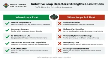
Where Loops Fall Short
- Pavement intrusion required: Installation means lane closures, saw-cutting, and traffic disruption
- No pedestrian detection: Loops detect metal — pedestrians register nothing
- Vulnerable to pavement damage: Heavy vehicles, utility cuts, and pavement shifts all threaten wire integrity
- No trajectory or turning movement data: A loop tells you a vehicle was there, not where it went or how it interacted with other road users
- Bicycles and motorcycles need extra attention: Standard configurations and sensitivity settings are insufficient for small metallic objects
The Decision Framework
Those limitations don't disqualify loops — they define their scope. Inductive loops remain the cost-effective, high-accuracy standard for vehicle counting and signal actuation at most intersections. Agencies should consider supplementary or alternative technologies when:
- Multimodal data is required (pedestrians, cyclists, turning movements)
- Pavement cuts are impractical (new concrete, bridge decks, historic pavement)
- Safety conflict analysis is needed (near-miss data, trajectory tracking)
- Above-ground sensor refresh makes economic sense during a broader corridor upgrade
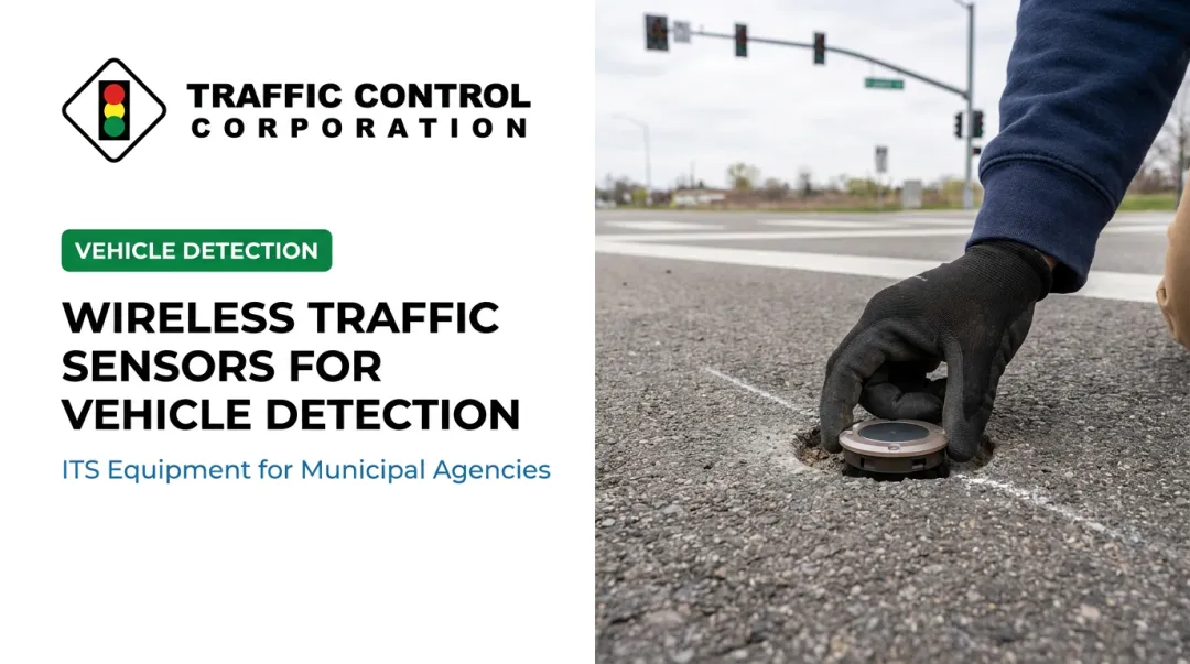
TCC distributes alternatives across each of those categories — including Econolite's Autoscope OptiVu AI video detection, EPIQ RADAR FMCW radar, Ouster LiDAR, and AccuSense in-ground wireless sensors — to help agencies match the right detection technology to each site's specific requirements.
Frequently Asked Questions
What is an inductive loop sensor?
An inductive loop sensor is an electromagnetic vehicle detection system consisting of wire coils embedded in pavement. It detects vehicles by sensing the drop in inductance that occurs when a metal vehicle passes over or stops within the loop's magnetic field, triggering a signal to the traffic controller.
What does an induction loop measure?
An induction loop measures changes in inductance — the reduction in the loop's electromagnetic field caused by a vehicle's metal mass. The electronics unit translates this change into vehicle presence, passage, and occupancy data, and paired-loop setups add speed and classification capability.
How long do inductive loop sensors last?
When installation quality is high and pavement conditions are favorable, loops can often remain functional for 10–20 years — roughly the lifespan of the surrounding pavement. Service life depends heavily on sealant integrity, freeze-thaw exposure, splice quality, and pavement stability.
How are inductive loop sensors installed?
A narrow slot is milled into the pavement, the loop wire is laid in the channel, and the slot is sealed with weatherproof sealant. The lead-in cable runs from the loop to a pull box, then continues to the electronics unit in the signal controller cabinet.
Can inductive loops detect bicycles and motorcycles?
Standard loops can detect motorcycles when sensitivity is properly calibrated. Diamond-shaped loops installed in dedicated bike lanes are designed specifically for bicycle detection. Very small metallic masses or non-metallic frames may not register reliably.
What are the main alternatives to inductive loop sensors?
Common alternatives include video/AI camera systems, FMCW radar, LiDAR, magnetometers, and passive infrared sensors. Each differs in installation requirements, data richness, weather performance, and pedestrian/cyclist detection capability — selection depends on the intersection type and agency priorities.